
Support the intended base surface
Machine a rigid, flat seat from the exact outline. Locate the sensor without squeezing the case or bypassing the sensing load path.
Specify a button compressive load cell with thread when the fixture needs positive location. For heated presses and moulds, treat the sensor body, cable and electronics as separate thermal zones.
Request a configuration review ↗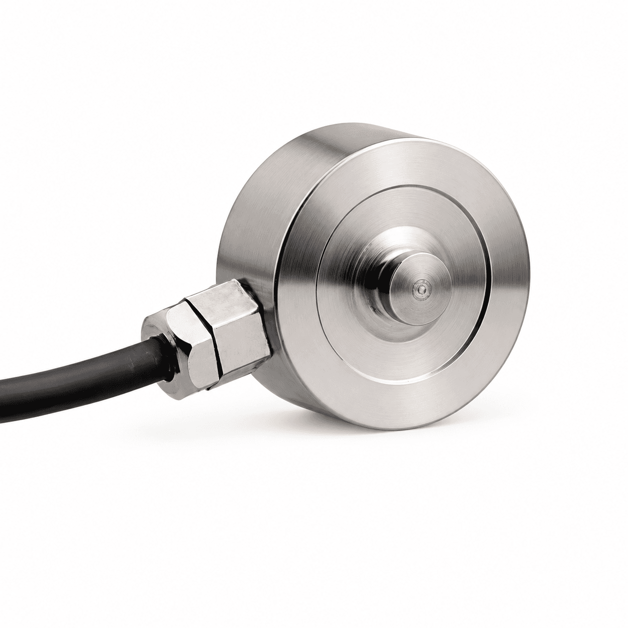
| Outer diameter (OD) | Height (H) | Series / fit | Button radius | Capacity (N / kgf / lbf) |
|---|---|---|---|---|
| Ø12.7 / Ø19 / Ø25.4 mm | Drawing-specific; 6.4 / 9.5 mm options | MT-BLC-LBM ↗Press-fit tooling & industrial fixtures | Spherical; drawing-specific | 50 N / 5.099 kgf / 11.24 lbfto 10,000 N / 1,019.716 kgf / 2,248.089 lbf |
| Drawing-specific | Drawing-specific | MT-BLC-THD ↗Switch, stop & ejector-pin testing | Spherical; drawing-specific | 10 N / 1.02 kgf / 2.248 lbfto 5,000 N / 509.858 kgf / 1,124.045 lbf |
Threaded retention reduces movement during setup, but it does not remove the need for an axial force path and a supported base. Confirm the thread pitch, engagement, torque and overall installed height from the exact model drawing.
High temperature miniature load cell configurations are reviewed for the actual body temperature, dwell time and thermal gradient. The −40°C to +180°C cable upgrade is a separate option; it does not extend the sensing element rating. Keep amplifiers outside the hot zone and agree temperature-dependent zero and span limits.
A compact sensor only measures correctly when the surrounding fixture supports it correctly.
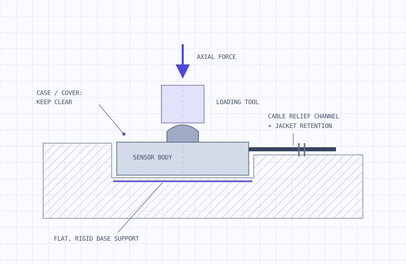
Machine a rigid, flat seat from the exact outline. Locate the sensor without squeezing the case or bypassing the sensing load path.
Align compression with the sensing axis. Keep the tool clear of the cover and outer case; a spherical top helps accommodate small alignment differences.
Provide a dedicated exit channel and jacket retention. Specify flexing, bend space and a strain-relief spring or sleeve with the configuration.
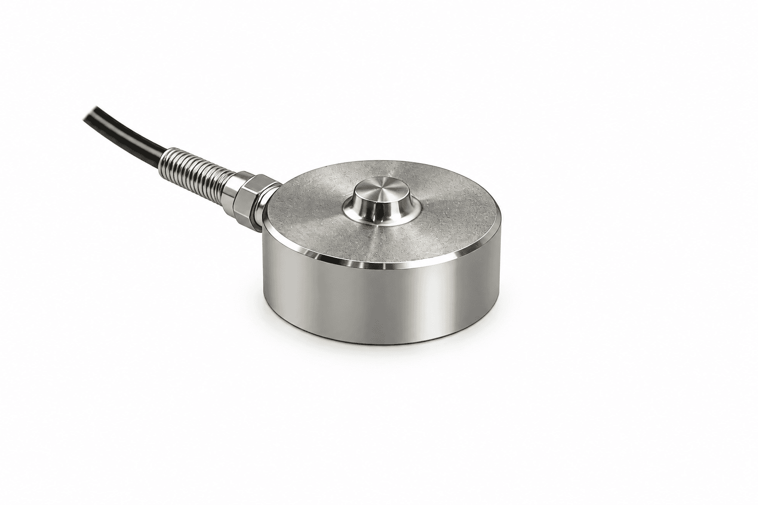
Press-fit tooling & industrial fixtures
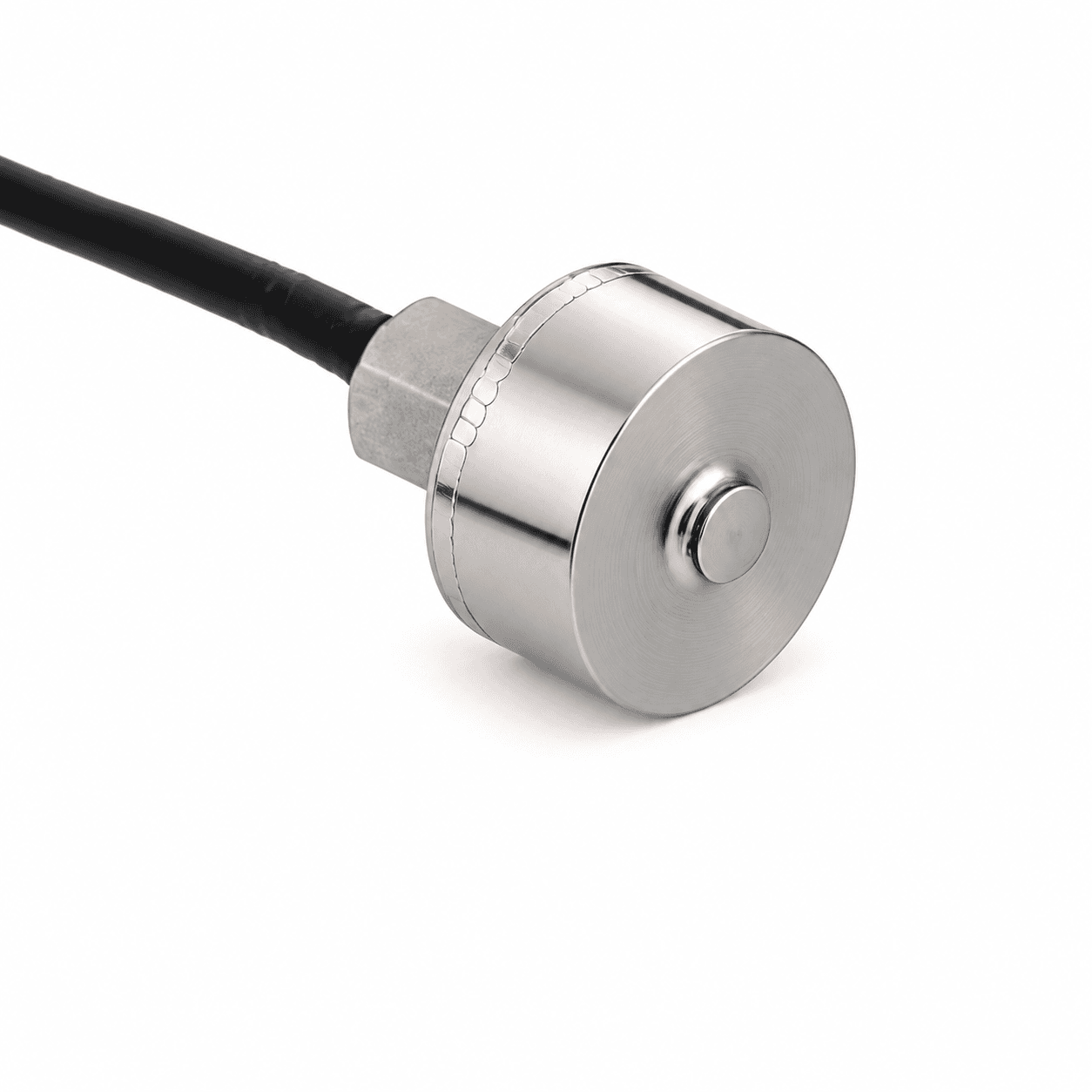
Switch, stop & ejector-pin testing
Need an application-specific answer?
Talk through your force path ↗
Include preload, normal compression peaks and credible overloads. Select a range that resolves the minimum force of interest while leaving mechanical margin, and add a fixture overload stop.
Kilograms describe mass. Use kgf when expressing force: 1 kgf = 9.80665 N. The tables show N, kgf and lbf together; dimensions and ratings remain model-specific.
Send the complete original model, drawing revision, capacity and electronics details. We review mechanical and electrical interfaces and agree a sample correlation test before compatibility is confirmed.
No. Cable, sensor body and amplifier ratings are separate. Request a +150°C or +200°C sensing configuration with the actual thermal conditions and agreed zero/span limits.
A bare mV/V bridge normally needs a compatible conditioner. Specify an MT-AMP-KIT with 0–10V, 4–20mA or an agreed RS485 interface, plus system calibration and force mapping.
Send OD × height, peak force and output. We’ll start with the fit.