MT-BLC-SUB01
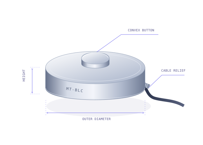
Subminiature load buttons
Robotics fingertips & miniature instruments
- Diameter
- Ø6 / Ø8 / Ø9.5 mm
- Capacity
- 1–250 N
Choose a button load cell with readout for portable checks, a USB interface for laboratory acquisition or a PLC amplifier for machine integration. Specify the sensor and electronics together for system calibration.
Request a configuration review ↗| Outer diameter (OD) | Height (H) | Series / fit | Button radius | Capacity (N / kgf / lbf) |
|---|---|---|---|---|
| Ø6 / Ø8 / Ø9.5 mm | 2.8–4 mm | MT-BLC-SUB ↗Robotics fingertips & miniature instruments | Spherical; drawing-specific | 1 N / 0.102 kgf / 0.225 lbfto 250 N / 25.493 kgf / 56.202 lbf |
| Ø12.7 / Ø19 / Ø25.4 mm | Drawing-specific; 6.4 / 9.5 mm options | MT-BLC-LBM ↗Press-fit tooling & industrial fixtures | Spherical; drawing-specific | 50 N / 5.099 kgf / 11.24 lbfto 10,000 N / 1,019.716 kgf / 2,248.089 lbf |
| Sensor selected separately | Module-specific | MT-AMP-KIT ↗Laboratory acquisition & PLC integration | Sensor-specific | Matched to selected sensor |
A bare bridge outputs a small differential voltage relative to excitation. It needs a compatible conditioner. USB provides digital acquisition; 0–10V and 4–20mA suit compatible PLC inputs; RS485 requires an agreed protocol and register map.
A paired configuration records sensor identity, full-scale force, zero, span and output mapping. Replacing the sensor, cable or amplifier can change the measurement chain and may require recalibration.
Robotics fingertips & miniature instruments
Press-fit tooling & industrial fixtures
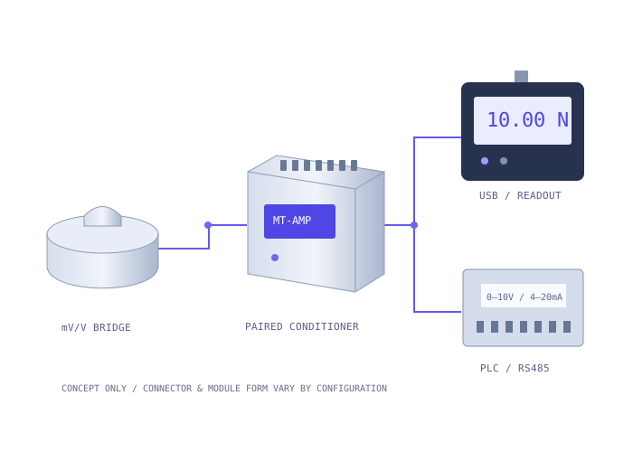
Laboratory acquisition & PLC integration
Need an application-specific answer?
Talk through your force path ↗
Include preload, normal compression peaks and credible overloads. Select a range that resolves the minimum force of interest while leaving mechanical margin, and add a fixture overload stop.
Kilograms describe mass. Use kgf when expressing force: 1 kgf = 9.80665 N. The tables show N, kgf and lbf together; dimensions and ratings remain model-specific.
Send the complete original model, drawing revision, capacity and electronics details. We review mechanical and electrical interfaces and agree a sample correlation test before compatibility is confirmed.
No. Cable, sensor body and amplifier ratings are separate. Request a +150°C or +200°C sensing configuration with the actual thermal conditions and agreed zero/span limits.
A bare mV/V bridge normally needs a compatible conditioner. Specify an MT-AMP-KIT with 0–10V, 4–20mA or an agreed RS485 interface, plus system calibration and force mapping.
Send OD × height, peak force and output. We’ll start with the fit.