Skip to content
MAGATOM / MICRO-FORCE SENSINGCompression sensing. Millimetre scale.
◎ButtonLoadCellsPRECISION IN EVERY NEWTON
Products by type ⌄
Subminiature load buttonsMT-BLC-SUBMiniature button load cellsMT-BLC-LBMThreaded button load cellsMT-BLC-THDMedical OEM force sensorsMT-BLC-MEDReadouts & USB kitsMT-AMP-KITCompare all series →Press-fit & switch testing →
Readouts & USBReplacement reviewCustom & OEMGuides
Request a quote ↗
☰
All productsSubminiature load buttonsMiniature button load cellsThreaded button load cellsMedical OEM force sensorsReadouts & USB kitsPress-fit & switch testingReplacement reviewCustom & OEMMounting & engineering guidesAbout MagatomRequest quote / sample ↗
Home/Products/MT-BLC-THD
MT-BLC-THD / SERIES

Threaded-Mount Button Compression Load Cell

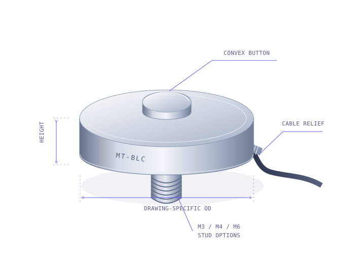
A stud or flange locates the sensor in repetitive switch, stop and mould ejector measurements. The mounting feature retains the body while force enters through the central convex button.
Configure & request quote ↗Series selection guide →
Outer diameter
Drawing-specific
Installed height
Drawing-specific
Mounting
M3 / M4 / M6 stud or custom flange
Accuracy envelope
±0.1–0.25% FS non-linearity
Concept of a convex compression load button with outside diameter, installed height and cable exit callouts
Engineering concept · not to scale · confirm model drawing
Envelope first

OD × height × compression capacity.

Series selection envelope — exact dimensions and capacity combinations require the model drawing.
Outer diameter (OD)Height (H)Series / fitButton radiusCapacity (N / kgf / lbf)
Drawing-specificDrawing-specificMT-BLC-THD ↗Switch, stop & ejector-pin testingSpherical; drawing-specific10 N / 1.02 kgf / 2.248 lbfto 5,000 N / 509.858 kgf / 1,124.045 lbf
10 N1.02 kgf / 2.248 lbf
20 N2.039 kgf / 4.496 lbf
50 N5.099 kgf / 11.24 lbf
100 N10.197 kgf / 22.481 lbf
250 N25.493 kgf / 56.202 lbf
500 N50.986 kgf / 112.404 lbf
1,000 N101.972 kgf / 224.809 lbf
2,000 N203.943 kgf / 449.618 lbf
5,000 N509.858 kgf / 1,124.045 lbf

Series options are not a full cross-product of every dimension and capacity. Button radius, tolerances, overload and model-specific performance are confirmed on the released drawing and quotation.

Integration review

Locate the sensor securely through repeated cycles.

Thread engagement

Confirm thread pitch, engagement depth and installation torque from the released drawing. Do not transmit installation torque through the fine cable.

Tactile testing

Control the actuator alignment, contact tip geometry and travel rate. An excessively large capacity can conceal the force changes you want to measure.

Hot tooling

Specify sensor body, cable, connector and amplifier temperatures separately. A high-temperature cable is not a high-temperature sensor approval.

17-4PH structure. A bridge signal built around your range.

Elastic element / button
Heat-treated 17-4PH stainless steel; 42–45 HRC loading surface target, configuration dependent
Nominal output / bridge
1–2 mV/V; 350 Ω / 700 Ω full bridge options
Hysteresis / repeatability
±0.1% RO design target; model-specific confirmation
Standard operating temperature
−20°C to +80°C; compensated range specified separately
Ingress protection
IP65 / IP67 configurations by model; confirm cable exit and sealing
High-temperature configurations
+150°C / +200°C options subject to body, cable and thermal validation
The load path matters

Load the convex button.
Give the cable room to move.

A compact sensor only measures correctly when the surrounding fixture supports it correctly.
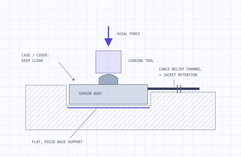
Cross-section concept showing axial loading on the central button, a supported sensor base and a separate cable relief channel
Mounting concept only. Base support, clearances and recess dimensions follow the selected model drawing.
01

Support the intended base surface

Machine a rigid, flat seat from the exact outline. Locate the sensor without squeezing the case or bypassing the sensing load path.

02

Keep contact on the central button

Align compression with the sensing axis. Keep the tool clear of the cover and outer case; a spherical top helps accommodate small alignment differences.

03

Relieve the fine shielded cable

Provide a dedicated exit channel and jacket retention. Specify flexing, bend space and a strain-relief spring or sleeve with the configuration.

Read the mounting notes ↗
Engineering RFQ / samples

Tell us the space.
We’ll help size the sensor.

Share the maximum diameter, installed height and compression range. We’ll review the force path, propose a series and confirm the drawing and output configuration.

What happens next
  1. Mechanical & electrical fit review
  2. Configuration and calibration proposal
  3. Sample quotation with confirmed lead time

Prefer email? Contact sales@magatom.com. Inquiries are received by our dedicated button load cell mailbox.

Configure the measurement package

Requested additions: US$0 / unit, before sensor price, shipping and taxes. Options and final price are confirmed in the quotation. The cable option does not change the sensor body’s temperature rating.

By sending this request, you agree to our privacy policy. Please keep confidential drawings out of this form; we can arrange a private exchange.

Complete the compression measurement.

MT-BLC-SUB — Subminiature load buttons ↗MT-BLC-LBM — Miniature button load cells ↗MT-BLC-MED — Medical OEM force sensors ↗MT-AMP-KIT — Readouts & USB kits ↗Review an existing sensor replacement ↗
◎ButtonLoadCellsMAGATOM DYNAMICS

A Specialized Micro-Force Sensing Division of Magatom Dynamics Co., Ltd.

Shenzhen, China · Serving global engineering teams

[email protected] ↗

Compression load buttons

Subminiature load buttonsMiniature button load cellsThreaded button load cellsMedical OEM force sensorsReadouts & USB kits

Engineering & procurement

FUTEK / Burster / Minebea reviewCustom & medical OEMMounting & engineering guidesAbout our divisionRequest quote / sample
© 2026 Magatom Dynamics Co., Ltd.
PrivacyTermsCookies