MT-BLC-LBM01
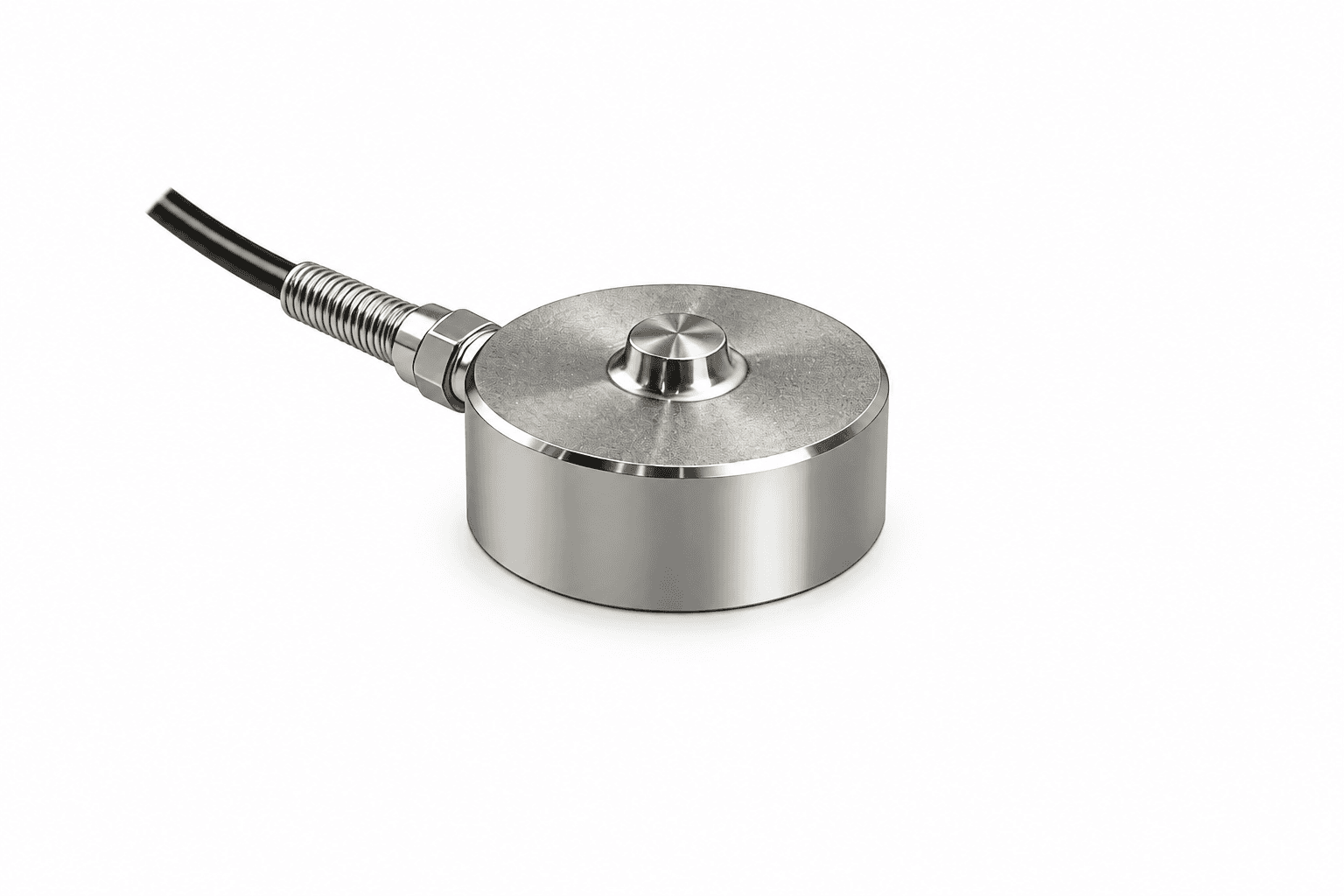
Miniature button load cells
Press-fit tooling & industrial fixtures
- Diameter
- Ø12.7 / Ø19 / Ø25.4 mm
- Capacity
- 50–10,000 N
Select a compact compression channel for a constrained battery fixture, with explicit preload, fixture stiffness and thermal error budgets.
Request a configuration review ↗| Outer diameter (OD) | Height (H) | Series / fit | Button radius | Capacity (N / kgf / lbf) |
|---|---|---|---|---|
| Ø12.7 / Ø19 / Ø25.4 mm | Drawing-specific; 6.4 / 9.5 mm options | MT-BLC-LBM ↗Press-fit tooling & industrial fixtures | Spherical; drawing-specific | 50 N / 5.099 kgf / 11.24 lbfto 10,000 N / 1,019.716 kgf / 2,248.089 lbf |
| Sensor selected separately | Module-specific | MT-AMP-KIT ↗Laboratory acquisition & PLC integration | Sensor-specific | Matched to selected sensor |
| Ø12.7 / Ø19 / Ø25.4 mm request envelopes | Drawing and thermal configuration specific | MT-BLC-LBM-HT ↗Press-fit tooling & industrial fixtures | Spherical; drawing-specific | 50 N / 5.099 kgf / 11.24 lbfto 10,000 N / 1,019.716 kgf / 2,248.089 lbf |
Measured swelling force depends on the stack stiffness and the displacement allowed by the fixture. Record cell format, contact plate geometry, fixture stiffness and initial compression so results from different fixtures can be interpreted.
Heat reaches the load button through platens and mounting plates. Log temperature close to the body and allow a defined thermal soak. Agree a zero and sensitivity characterisation cycle before interpreting small changes during charging or heating.
Store raw or defined filtered force, elapsed time, local temperature and charge-cycle identifiers. Keep amplifier excitation and output mapping in the test record. Compare loaded and unloaded thermal runs where the fixture allows.
Press-fit tooling & industrial fixtures
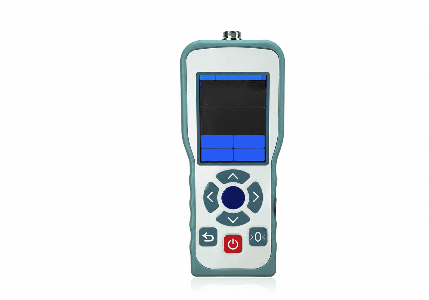
Laboratory acquisition & PLC integration

Press-fit tooling & industrial fixtures
Need an application-specific answer?
Talk through your force path ↗
Include preload, normal compression peaks and credible overloads. Select a range that resolves the minimum force of interest while leaving mechanical margin, and add a fixture overload stop.
Kilograms describe mass. Use kgf when expressing force: 1 kgf = 9.80665 N. The tables show N, kgf and lbf together; dimensions and ratings remain model-specific.
Send the complete original model, drawing revision, capacity and electronics details. We review mechanical and electrical interfaces and agree a sample correlation test before compatibility is confirmed.
No. Cable, sensor body and amplifier ratings are separate. Request a +150°C or +200°C sensing configuration with the actual thermal conditions and agreed zero/span limits.
A bare mV/V bridge normally needs a compatible conditioner. Specify an MT-AMP-KIT with 0–10V, 4–20mA or an agreed RS485 interface, plus system calibration and force mapping.
Send OD × height, peak force and output. We’ll start with the fit.