Skip to content
MAGATOM / MICRO-FORCE SENSINGCompression sensing. Millimetre scale.
◎ButtonLoadCellsPRECISION IN EVERY NEWTON
Products by type ⌄
Subminiature load buttonsMT-BLC-SUBMiniature button load cellsMT-BLC-LBMThreaded button load cellsMT-BLC-THDMedical OEM force sensorsMT-BLC-MEDReadouts & USB kitsMT-AMP-KITCompare all series →Press-fit & switch testing →
Readouts & USBReplacement reviewCustom & OEMGuides
Request a quote ↗
☰
All productsSubminiature load buttonsMiniature button load cellsThreaded button load cellsMedical OEM force sensorsReadouts & USB kitsPress-fit & switch testingReplacement reviewCustom & OEMMounting & engineering guidesAbout MagatomRequest quote / sample ↗
Home/Subminiature Load Buttons for Ø6–Ø10 mm Spaces
Miniature envelope / axial compression

Subminiature Load Buttons for Ø6–Ø10 mm Spaces

For a tiny load cell, the surrounding mechanism matters as much as the sensor. Compare outside diameter, installed height, loading contact and the cable relief before choosing a force range.

Request a configuration review ↗
Series selection envelope — exact dimensions and capacity combinations require the model drawing.
Outer diameter (OD)Height (H)Series / fitButton radiusCapacity (N / kgf / lbf)
Ø6 / Ø8 / Ø9.5 mm2.8–4 mmMT-BLC-SUB ↗Robotics fingertips & miniature instrumentsSpherical; drawing-specific1 N / 0.102 kgf / 0.225 lbfto 250 N / 25.493 kgf / 56.202 lbf
01

Start with OD × height, then allow cable clearance

The MT-BLC-SUB design envelope starts at Ø6 mm × H2.8 mm, with Ø8 and Ø9.5 mm options. These are series options rather than a promise that every force rating fits every envelope.

  • Send the maximum installed diameter and total height, including the loading contact.
  • Show the cable exit direction and the minimum bend space.
  • Request the exact capacity-specific outline and spherical button radius.
02

1–250 N capacity options for small contact forces

A lower capacity can improve sensitivity to small load changes, but it must survive the actual preload, contact peaks and fixture setup. Define the overload stop and maximum expected force before reducing the sensor range.

The load path matters

Load the convex button.
Give the cable room to move.

A compact sensor only measures correctly when the surrounding fixture supports it correctly.
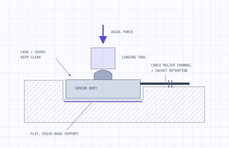
Cross-section concept showing axial loading on the central button, a supported sensor base and a separate cable relief channel
Mounting concept only. Base support, clearances and recess dimensions follow the selected model drawing.
01

Support the intended base surface

Machine a rigid, flat seat from the exact outline. Locate the sensor without squeezing the case or bypassing the sensing load path.

02

Keep contact on the central button

Align compression with the sensing axis. Keep the tool clear of the cover and outer case; a spherical top helps accommodate small alignment differences.

03

Relieve the fine shielded cable

Provide a dedicated exit channel and jacket retention. Specify flexing, bend space and a strain-relief spring or sleeve with the configuration.
Read the mounting notes ↗

Explore the matching sensor series.

MT-BLC-SUB01
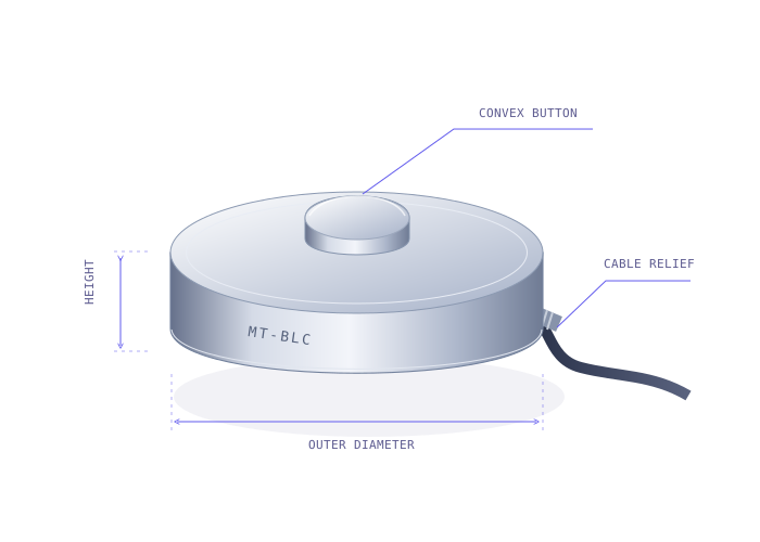
Concept of a convex compression load button with outside diameter, installed height and cable exit callouts
Engineering concept · not to scale · confirm model drawing

Subminiature load buttons↗

Robotics fingertips & miniature instruments

Diameter
Ø6 / Ø8 / Ø9.5 mm
Capacity
1–250 N
Before you freeze the drawing

Five questions about
compression measurement.

Need an application-specific answer?
Talk through your force path ↗

How do I choose a button load cell capacity?+

Include preload, normal compression peaks and credible overloads. Select a range that resolves the minimum force of interest while leaving mechanical margin, and add a fixture overload stop.

Are kg, kgf and N interchangeable?+

Kilograms describe mass. Use kgf when expressing force: 1 kgf = 9.80665 N. The tables show N, kgf and lbf together; dimensions and ratings remain model-specific.

Can you supply a drop-in replacement?+

Send the complete original model, drawing revision, capacity and electronics details. We review mechanical and electrical interfaces and agree a sample correlation test before compatibility is confirmed.

Does a high-temperature cable upgrade change the sensor rating?+

No. Cable, sensor body and amplifier ratings are separate. Request a +150°C or +200°C sensing configuration with the actual thermal conditions and agreed zero/span limits.

Can a load button connect directly to a PLC?+

A bare mV/V bridge normally needs a compatible conditioner. Specify an MT-AMP-KIT with 0–10V, 4–20mA or an agreed RS485 interface, plus system calibration and force mapping.

From envelope to measurement

A few millimetres.
A better force measurement.

Send OD × height, peak force and output. We’ll start with the fit.

Request a quote / sample ↗
◎ButtonLoadCellsMAGATOM DYNAMICS

A Specialized Micro-Force Sensing Division of Magatom Dynamics Co., Ltd.

Shenzhen, China · Serving global engineering teams

[email protected] ↗

Compression load buttons

Subminiature load buttonsMiniature button load cellsThreaded button load cellsMedical OEM force sensorsReadouts & USB kits

Engineering & procurement

FUTEK / Burster / Minebea reviewCustom & medical OEMMounting & engineering guidesAbout our divisionRequest quote / sample
© 2026 Magatom Dynamics Co., Ltd.
PrivacyTermsCookies