Off-Centre Loading: A Button Load Cell Fixture Test Plan
Plan a repeatable axial and offset loading review without assuming a spherical top eliminates eccentric force errors.
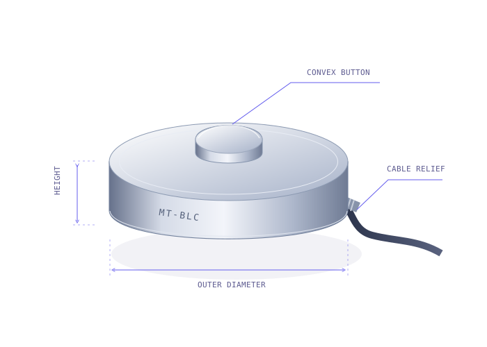
Define the load path and allowed offset
A convex button can help establish a repeatable contact point with a flat tool. It does not eliminate moments, friction or lateral forces. Document the intended support surface and define the allowed offset and angle at the tool; do not choose a generic tolerance from a photograph.
Establish an axial baseline
Use the approved fixture and a suitable force reference. Apply agreed force points along the sensing axis, then unload. Record output, temperature, excitation, mounting orientation and zero recovery. This establishes a baseline for the same assembly, not a universal error specification.
- Use several points over the intended operating range.
- Record loading and unloading directions separately.
- Repeat enough cycles to distinguish setup variation from persistent error.
Change one fixture condition at a time
Repeat at the agreed small offsets and angles within the safe test plan. Keep support, loading points and electronics unchanged. Compare each point with the axial baseline at the same reference force.
Offset deviation (%) = 100 × (offset reading − axial reading) / reference force
- Inspect for contact with the outer cover or fixture wall.
- Stop if the tool slips or side load is uncontrolled.
- Do not treat a zero-force percentage as meaningful; use absolute force error near zero.
Write an acceptance criterion before testing
State the maximum allowed force error over the specified offset, load and temperature conditions. A measured pass applies to that documented assembly and range. Request model-specific deflection, overload and installation instructions before releasing the tooling.
For a drawing-specific review, send your installation and force requirements ↗.
← All engineering guides