Mounting Recess & Cable Relief for Button Load Cells
Plan an axial loading path, rigid base support and protected cable exit for a miniature compression load button.
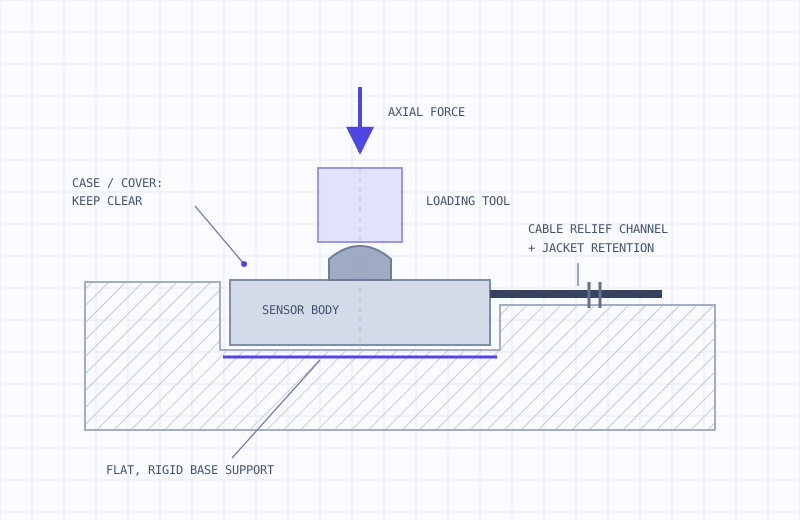
Start from the selected model’s base support
A button load cell is a sensing structure, not a general-purpose spacer. Its intended base contact may be a defined annular surface or another model-specific geometry. Use the approved outline drawing to identify that surface before machining the recess.
- Keep the support flat, rigid and clean.
- Check the allowed retention features and the total installed stack.
- Leave room for the cable exit and its specified protection sleeve.
- Set recess clearance from the released drawing rather than a generic fit allowance.
Keep the tool on the central convex surface
The tool should load the spherical button along the sensing axis. Contact on the cover or outer case can bypass the sensing path or damage the sensor. A spherical top can reduce the effect of small angular differences, but it does not permit uncontrolled side loads or arbitrary eccentric contact.
- Align the actuator and contact pad with the sensor axis.
- Maintain clearance between the loading tool and the surrounding cover.
- Add a mechanical stop for credible overloads.
- Verify the assembled fixture with a controlled compression cycle.
Retain the cable jacket outside the recess
Fine conductors need a separate exit channel. Hold the jacket at a suitable point so handling and motion do not pull on the sensor termination. Specify the expected flex cycle, bend space, fluid exposure and temperature so the cable and relief can be reviewed together.
- Avoid pinching the cable under a mounting screw or fixture plate.
- Route signal wiring separately from motor and switching power conductors.
- Follow the agreed shield termination and grounding arrangement.
- Check the cable through the full travel of the machine or finger.
What to send for an installation review
Provide a section view showing sensor support, the moving tool, cable exit, maximum OD, installed height, normal load, preload, peak load and the overload stop. Ask for the model-specific drawing, button radius and installation instructions before releasing the fixture.
For a drawing-specific review, send your installation and force requirements ↗.
← All engineering guides