From mV/V to USB, Readout or PLC Force Data
Understand load button bridge output, excitation, amplifier mapping and paired calibration before connecting a miniature sensor.
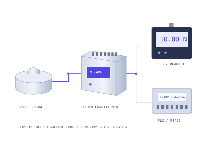
Rated mV/V is relative to bridge excitation
A nominal 2 mV/V sensor excited at 5 V produces approximately 10 mV at rated compression. That value describes nominal span; zero balance, actual calibrated sensitivity, wiring and allowable excitation still come from the sensor configuration.
Nominal full-scale signal = rated mV/V × excitation V
Choose the destination before the conditioner
A handheld readout suits portable checks; USB suits compatible computer acquisition; 0–10V and 4–20mA connect to appropriate analogue inputs; RS485 requires an agreed protocol. A bare mV/V sensor should connect to a bridge-capable input, not an ordinary voltage input configured for a much larger range.
- Confirm bridge resistance, excitation, pinout and shield termination.
- Specify full-scale force and analogue output mapping.
- Check PLC or USB sampling rate, filtering and required response time.
- Keep electronics outside hot tooling when their rating is lower than the sensor’s.
Converter bits do not establish effective force resolution
A 24-bit ADC describes the converter architecture. Real usable resolution depends on sensor sensitivity, noise, excitation stability, bandwidth, filtering and the mechanical environment. For several fingertips, also specify simultaneous sampling or the acceptable timing skew between channels.
Calibrate and identify the complete chain
Factory pairing should identify the sensor and module, nominal range, zero, span, calibration conditions and output mapping. Keep the paired components together. A cable, connector, sensor or module change can alter the measurement chain and should trigger an assessment of recalibration needs.
For a drawing-specific review, send your installation and force requirements ↗.
← All engineering guides